History of Remote Sensing: Landsat (ne: Earth Resources Technology Satellite)
Contents
The sources of many of the images displayed throughout this Tutorial is the ERTS-1 (renamed Landsat) and subsequent Landsats originally developed by NASA and operated by them and/or several other agencies from 1972 through the present (Landsat-7). The Landsat program is described and the orbital and instrumental parameters for this series of satellites are given. Discussion of Landsat’s two prime sensors, the MSS and TM, and examples of images produced from each is deferred to the next 6 pages.
History of Remote Sensing: Landsat (ne: Earth Resources Technology Satellite)
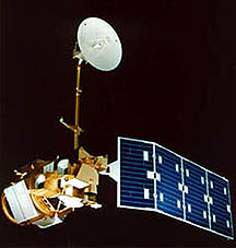
Renamed Landsat, ERTS-1 was the first in this series (seven to date) of Earth-observing satellites that have permitted continuous coverage of most of Earth’s surface since 1972. Launch dates are: Landsat 1, July 23, 1972; 2, January 22, 1975, 3, March 5, 1978; 4 , July 16, 1982, 5, March 1, 1984 (Landsat 6, launched later, failed to operate); and 7, April 15, 1999. (As of May 1999, only Landsats 5 and 7 are operational, i.e., acquiring data; the older ones have been shut down.). To help to visualize this information, we repeat an illustration first shown on page 1 of the Overview:

The orbital conditions for Landsat 1 are depicted in this illustration and described in the next paragraph.
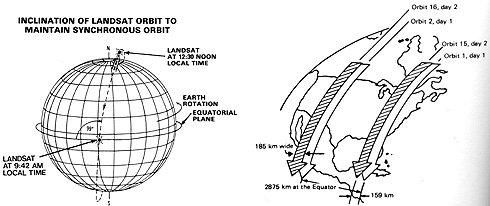
The first three Landsats orbited at an altitude of 570 miles (923 km); 4 and 5 at 435 miles (705 km). The orbits of all Landsats are near-polar (inclined 9.09° from a longitudinal line) and Sun-synchronous (pass every time over the equator between 9:30 and 10:00 AM), making 14 passes in descending mode (southward from the North pole in the daylight mode) each day (about 103 minutes for a complete orbital circuit). After any given orbit, the spacecraft will occupy its next orbit some 1775 miles (2875 km) to the west; on the next day, the orbits are so configured so that orbit 15 has displaced westward by 98 miles (159 km) at the equator. Landsats 1-3 will reoccupy almost precisely the same orbit after 252 such orbits, or 18 days later; Landsats 4 and 5 reoccupy on a 16 day cycle. Under the above orbital conditions, and with an angular field of view if 11.58 ° the width of a Landsat MSS scene is 185 km (114 statute or 100 nautical miles). The continuing orbital strip is cut every 185 km to produce a given image’ length. These same frame dimensions hold for the Landsat Thematic Mapper (TM) images, discussed later.
The orbits of the Landsats are termed “paths” and the location of individual images along these paths are fixed by a row system. This Worldwide Reference System is described in some detail at this U.S. Geological Survey web site.
` <>`__I-19 Approximately how many square miles are enclosed are enclosed in a Landsat MSS frame? Square kilometers? Acres? (Note: there are about 640 acres in a square mile.)`ANSWER <answer.html#I-20>`__
All the Landsats follow a near-polar orbit (inclined about 98° to the equator; passing within 8° of the poles) and are sun-synchronous, meaning the orbit precesses about Earth at the same angular rate as Earth revolves about the Sun. Thus, it crosses the equator (traveling from North to South) each day between 9:30 and 10:00 A.M., local time. Landsats 1-3 make 14 full orbits (each successive one displaced 2875 km [ 1785 miles] to the west) each day (three over the U.S.), and after 252 orbits in 18 days, they repeat their previous ground tracks. Landsats 4-5, from a lower altitude (705 km [438 miles]), cover the same ground track again every 16 days, after 233 orbits. It takes about 11,000 scenes to fully image the entire Earth’s land surface (except for polar regions).
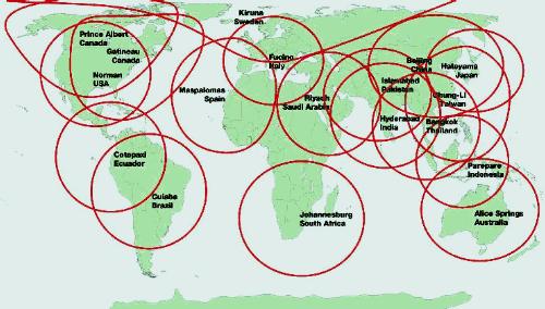
Since the first Landsats, their success and the obvious value of the information they send back have prompted many countries to set up direct-readout receiving stations so as to obtain the raw data in near real time without depending on the NASA processing centers. These stations are charted by NASA and must agree to distribute the data to users in their region. Here is a map of currently active stations:
In the U.S., the primary receiving station for Landsats 1-3 was at Goddard Space Flight Center. Later Landsats were operated by different organizations and another major receiving station was established at the United States Geological Survey’s EROS Data Center in Sioux Falls, S.D. Processing at these places include reformatting of the raw data that involves orbital, geometric, and radiometric corrections. For years, the output data were distributed on 9-track Computer Compatible Tapes (CCTs) but today data for Landsat and the EOS satellites are put on 8 mm, 4 mm, DLT, CD-ROM and 3 1/2 disk storage units.
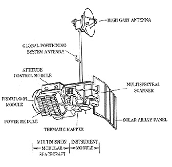
Landsats 4, 5 (and 6) carried, in addition to the MSS, a new instrument called the Thematic Mapper. Here are an artist’s sketch of the Landsat 4 spacecraft and a drawing with labeled components, which point to the notable differences from the previous Landsats:
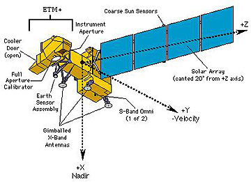
Landsat 7 mounts only a single payload, the Enhanced Thematic Mapper (ETM+). The ETM+ includes not only the 7 TM bands (the thermal band [6] has 60 m resolution), but also a panchromatic band that is capable of 15 m resolution. This artist’s rendition shows that the spacecraft differs in general construction from the previous “birds”.
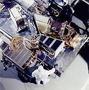
Compare this view of Landsat 7 in its assembly room with the view of Landsat 1 at the top of the page:
As of this writing (March 2003) Landsats 5 and 7 are still operational and returning data.
Primary Author: Nicholas M. Short, Sr. email: nmshort@nationi.net