App description
Super capacitor working time
The calculator determines the working time in the time keeping state when the super capacitor is
powered according to the starting voltage and the ending voltage, the discharging current and the
electric capacity of the capacitor.
among them:
The maximum Vcap corresponds to the maximum value of VCC, and the related data
can be consulted, namely: (VCC maximum value) - (diode voltage drop)
The minimum Vcap is the minimum operating voltage of the RTC oscillator. Refer to the relevant data
sheet.
The maximum value of IBAT is the maximum current of the battery, and the relevant data can
be consulted.
The typical value of IBAT is the typical battery current defined at 25 ° C and the nominal
supply voltage, and the relevant data can be found.
The maximum value of VBAT is the maximum voltage of the VBAT pin, which can be consulted.
IBAT maximum and IBAT typical values are used to calculate the maximum IBAT
and typical IBAT work Time (hours). When calculating the working time, assume that the IBAT
current remains constant, regardless of the voltage at the battery input pin.
When calculating the operating time under linear IBAT, it is assumed that the oscillator current is
proportional to the input voltage, which is expressed as a resistance characteristic. The equivalent resistance
of the circuit is calculated using the maximum value of IBAT and the maximum value of VBAT
provided in the data sheet, which is used to calculate the battery backup time.
Specification sheet example
Recommended DC operating conditions (TA = -40°C to +85°C)
| Parameter |
Symbol |
Condition |
Minimum value |
Typical value |
Maximum value |
Point position |
| Supply voltage |
VCC |
|
2.7 |
3.0 |
3.3 |
V |
| Supply voltage |
VBAT |
|
1.3 |
3.0 |
3.7 |
V |
| Table 1 |
|
DC electrical characteristics (TA = -40°C to +85°C)
| Parameter |
Symbol |
Condition |
Minimum value |
Typical value |
Maximum value |
Point position |
| Battery current |
VBAT |
|
|
600 |
1000 |
nA |
| Table 2 |
|
Typical RTC trickle charger internal circuit
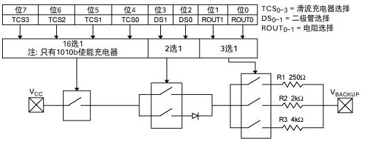
Figure 1
Note: The diode selection circuit of some devices allows the selection of 1 or 2 series diodes,
and some devices can select 0 or 1 diodes. Assume that each diode has a voltage drop of 0.7V.
Typical RTC circuit with supercapacitor backup power supply

Figure 2