16. Discussion on the problems caused by offset compensation in WebGIS
16.1. Background
In the previous chapter, I explained the implementation of map translation, And I finally asked two questions:
A.After the map pans, the XY of the canvas of the vector layer changes, and can the features be displayed correctly on the canvas by converting the screen coordinates from the geo-coordinate stomorphic formula?
B.Does the vector layer canvas’s origin coordinate XY need to be restored to the initial (0,0)?
The answer I give to these two questions is: no and needs.
In this chapter, we will explain in detail the reasons for these two answers.
16.2. What is offset compensation?
As the map pans, we did two things: one was changed to MapCanvas’s origin coordinate xY, and the second was a change in the actual geographic extent of the screen at this time. The detailed implementation process and formula can refer to the design and implementation of the translation function in the previous chapter WebGIS.
Both operations require a common parameter, the operation offset (moveX, moveY). However, the action offset is not an offset offset at this point. Offset compensation is the overall offset for the initial coordinates (0,0), at which point the canvas’s upper-left coordinate XY, which we use as “sumMoveX, sumMoveY).
16.3. Impact of offset compensation
16.3.1. Problems that occur if offset compensation is not taken into account
Suppose, at this point, the map’s canvas origin has been translated (sumMoveX, sumMoveY), and when we use the vector service on the geographic or business service side again, we first convert the geographic coordinates in Geometry to the screen coordinates in Geometry, Then add the features drawn with the screen coordinates to the canvas. But here’s the problem, and we’ll find that the features at this point are not where we want them to be (the actual coordinates), but are shifting elsewhere. This is also a complete description of our first problem.
16.3.2. The cause of this problem
1 Review the equation for the interconversion of screen and geographic coordinates
Before we discuss this, it is necessary to look back at the formula i gave in chapter 10 for the interconversion of screen and geographic coordinates:
A.Screen coordinates converted to geographic coordinates
geoXY.x = screenGeoBounds.left + screenX * sliceLevelLength / tileSize;
geoXY.y = screenGeoBounds.top - screenY * sliceLevelLength / tileSize;
B.Geocoordinates converted to screen coordinates
screenXY.x = (geoX - screenGeoBounds.left)/(sliceLevelLength/ tileSize);
screenXY.y = (screenGeoBounds.top - geoY)/(sliceLevelLength/ tileSize);
GeoXY represents geographic coordinates, screenXY represents screen coordinates, screenGeoBounds represents screen geographic extent, and Sliece Level Lenth indicates the actual geographic length represented by a tile at the map level. TileSize represents the pixel size of a tile.
2 The problem of generating offset stoics from formula analysis
We look closely at the formula for converting geographic coordinates to screen coordinates, which is based on subtracting the geographic coordinates represented by the upper-left corner of the screen container at this time, and then dividing the geographic length represented by one pixel to arrive at the screen coordinates relative to the coordinates in the upper-left corner of the screen container.
Look at my description, repeatedly mentioned is the screen container upper-left coordinates, what is the screen container upper-left coordinates? Let’s look at the translation schematic I gave in the previous chapter:
.. figure:: img/img_1.png
The screen coordinates in the upper left corner of the container are the coordinates (0,0) that overlap the initial and canvas upper-left point A.
So, when we add a feature relative to (0,0) to a canvas that has changed to (sumMoveX, sumMoveY) in the upper left corner, the problem of the feature position shift occurs.
16.3.3. How to fix this offset issue
Knowing the problem that caused the offset, we just need to cure the problem. That is, when we change the geographic coordinates in the vector data to the screen coordinates, subtract an offset compensation.
That is:
ScreenXY=geoXYToSreenXY(geoXY)-sumMoveXY
At the code level, the screen coordinates that are converted are subtracted from the offset compensation when drawn.
16.4. When does the offset compensation zero?
To figure this out, we have to look again at the coordinate conversion formula. An important parameter is involved in this formula, the sliceLevelLength, the actual geographic length represented by the tile length at the current map level.
Imagine, when our map level changes, so does this parameter sliceLevelLength, and if sumMoveXY is still the previous number, then sumMoveXY represents The actual geographic length is no longer the correct geographical length.
This can cause a problem, and after the map level changes, the converted screen coordinates will be offset if you continue to use the previous sumMoveXY value.
At this point, if we adopt this approach, after the map level change, all sumMoveXY is reduced to 0, that is, to return to the state of no offset, it is a good solution to the location offset caused by the retention of the sumMoveXY value.
At the code level, a zoom event is thrown each time the map changes in rank, and the layer should listen to the event, and then change the top corner coordinate XY of the layer (canvas) to 0.
16.5. Further explore the nature of offset compensation and the problems it causes
16.5.1. Ask a question
Here, I’ll continue to ask two questions:
A.This hope that every mouse click can draw a dot in the mouse click place, but when the map is dragged, the mouse click shards on the map, but did not draw the dot in the click place, but offset.
B.Also want to click the mouse can draw a dot where the mouse click, even if you do not drag the map, when the mouse click on the features that have been drawn, found that the dot is now drawn offset to other places.
16.5.2. Analysis of experimental and experimental results
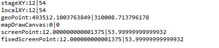
In answering the above two questions, I will first give a set of experimental data.
stageXY:Coordinates of the global stage;
localXY: Local coordinate system;
geoPoint:Geographical coordinates at this time;
mapDrawCanvas:The origin coordinates of this layer (Canvas);
screenPoint:Convert geographic coordinates to coordinates after screen coordinates;
fixedSreenPoint:Correction coordinates by subtracting screenPoint offset;
1)When the map is not dragged, i.e. when there is no offset compensation:
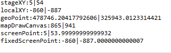
2)When you drag the map, when there is offset compensation:
1 Conclusion 1 - Screen coordinates for coordinate conversion are best stageXY
StageXY and screenPoint, which convert geographic coordinates to screen coordinates, are a good match without dragging the map and dragging the map. The reason, we carefully looked at the geographic coordinates into the formula of screen coordinates is not difficult to understand, because the translated screen coordinates are relative to the (0,0) coordinates, and this mapCanvasCanvas corresponding to the stage XY coordinates are relative to (0,0).
This conclusion tells us that the screen coordinates used for coordinate conversion are best stageXY.
2 Conclusion 2 - The screen coordinates of the conversion must be subtracted from the offset before they are equal to the localXY at this time
Observation of the experimental conclusion, the screenPoint minus the offset of the fixed ScreenPoint to remove the minimum error is equal to localXY. If you want to draw in a container, you must use its localXY coordinates.
3 Conclusion 3-Offset is the origin of the container (mapDrawCanvas .x, mapDrawCanvas .y)
We found that when the container (mapDrawCanvas) of origin coordinates (mapDrawCanvas .x,mapCanvasCanvas After the .y) change, the localXY obtained under the local coordinate system also has a related change. This offset allows you to use the container’s origin directly.
16.5.3. Problem solving
From Conclusion 1, we can know that the coordinates used for coordinate transformation are preferably stageXY.
The reason for problem 1 is to use localXY as the screen coordinate, then convert localXY to geographic coordinates and save it. After the map is panned, the geographic coordinates saved at this time are no longer the correct geographic coordinates, so the features are offset when they are drawn.
The reason for the problem 2 is that when we click on an feature, the localXY obtained at this time is no longer relative to the local coordinates of the container mapDrawCanvas, but relative to the local coordinates of the clicked feature. So there will be a very serious offset after the coordinate transformation.
16.6. Summary
In this chapter, we detail the nature of the offset compensation and its problems and solutions. In this chapter, we mentioned a lot of things that have been mentioned before, including coordinate transformation and the nature of translation. Finally, I gave a simple experimental data to further explain the nature of the offset compensation.
In the next chapter, we will discuss the algorithms, design, and implementation involved in the length measurement tool and the area measurement tool in the toolbar. I hope everyone will continue to pay attention.