11. Design of Features in WebGIS
11.1. Preface
In GIS features are generally divided into point features, line features, polygon features, and symbol features (special point features). Correspondingly, layers can be divided into point layers, line layers, polygon layers, and label layers.From Chapter 9 to Chapter 10, I’ve explained what vector data is, the source of vector data, the construction of vector data, and the conversion between geographic and screen coordinates in vector data.After understanding these concepts and algorithms and processes, this chapter will begin to explain the final step before designing a vector layer to design features in WebGIS.
11.2. Thought of feature design
11.2.1. Demand
Features should have the following features:
(1) Shape that can draw out vector data.
(2)Ability to store attributes of vector data.
(3)Can respond to mouse events.
(4)Can respond to custom events, such as a custom set of map events.
(5)Ability to add into Canvas to form a vector layer.
(6)Features have many types, such as points, lines, faces, and so on.
11.2.2. Basic analysis
We have already explained the essence of features, UIComponent. Because UIComponent is a well-encapsulated class in the front-end language, we can just inherit it, so we can achieve the third and fifth requirements mentioned above.
(2)The Shape in the requirement that can draw the vector data. So you have to define a function like Draw to solve the first requirement.
(3)There is also a variable in the feature to store attributes, that is, FeatureInfo to solve the second requirement.
(4)The designed class also defines a function that listens for events and a function that removes listeners, namely: addMapEventListener and removeMapEventListener to solve the fourth requirement.
11.2.3. Extended analysis
1 Redraw
When the map is refreshed, such as zooming in and out, then the UIComponent must be redrawn, otherwise the Shape on the map will no longer indicate the correct position on the map, so there are two points to note about the design of the feature:
(1)Listen to zoom in and out of the map.
(2)Add the redraw function, the reDraw function. Trigger the redraw function when the local map zooms in and out.
2 Base class
The requirements mention that features have multiple types, and we need to design properties and functions that are related to them as a base class, the Feature class. Properties and classes that can be abstracted are:
(1)reDraw and Draw functions
(2)FeatureInfo Properties
(3)addMapEventListener and removeMapEventListener function
(4)Monitoring map zoom-out events, the implementation of this feature can be placed in the Feature’s constructor.
3 hook to main frame
In drawing shape, we need to use the function of converting geographic and plane coordinates to each other, i.e. geoXYToScreenXY and screenXYToGeoXY mentioned in the previous chapter. But these two methods are unlikely to be encapsulated in the Feature class. Because these two methods are common in the system, they do not exist specifically for the Feature class. So these two methods are in the main frame class, where I define this main frame as FrameMap. Therefore, our Feature class should also have a property that can be injected into the main frame, namely Map.
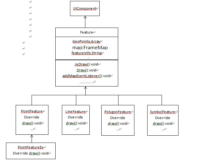
11.3. UML Design
Based on the above analysis, we are now starting to really design the features. We first define a Feature class that inherits from UIComponent and then defines a set of concrete base feature classes, such as PointFeature, LineFeature, and PolygonFeature, depending on the requirements. And if the requirements change, the original basic features can no longer meet the demand, you can inherit on the basic elements to further expand the basic feature class.
The following is a UML diagram of the last designed feature class:
11.4. Problems and solutions
11.4.1. How do you control the requirements in each of the base feature classes that require shapes to be rendered in different styles?
In practice, users may need to present the same feature differently. For example, the opposite features, sometimes need to show yellow, sometimes need to show blue and so on, and sometimes need to face features filled with mesh, sometimes need to move the face to change color, sometimes do not need to wait.
The solution to this problem is not to reinherit the underlying features for each requirement, and then modify the draw mode, if so, the code is too much repeated. In the design mode, we have a principle is to use the combination as much as possible, which can not inherit when as much as possible, can not inherit as far as possible, because inheritance is a kind of high coupling, derived classes and base classes are tightly tied together, flexibility is greatly reduced, and abuse of inheritance, will also make the inheritance tree become large and complex, difficult to understand and maintain. In this demand, there is no combination at the moment, but inheritance is even less needed.
Our solutions are generally:
First classify the requirements. Appearance: One is to change the color, the other is to change the internal structure of the feature. Behavior: One type requires some monitoring and related changes, and one type does not require some monitoring. This way we can add two common properties in a concrete feature class, such as a polygon class, one is DrewType and the other is ActionType. If you don’t want to put the burden of control behavior in the polygon class, we can also not define the ActionType. This class is designed with addMapEventListener and removeMapEventListener. It can be opened to the caller and judged by himself.
(2) Then in the Draw function, we control the drawing aspect by judging the DrawType. Each specific feature class has its own defined internal transparency (Sopacity), external transparency, and drawing properties such as internal fill colors (SColor) and outer fill colors, as well as fill icons (Symbol). Going back to the above requirements, we are one of the groups that wants to change the color of the features, and the other that we want to change the internal structure. Or suppose this is a requirement for polygon elements, and we define DrawType as 0 and 1. When TypeDraw is 0, we will draw using painting features such as Sopacity, opacity, Scolor, and color, all of which have public attributes with default values that the caller can set on their own. But when TypeDraw is 1, symbol is loaded, and then the way the polygon is drawn is changed to fill Symbol as an internal filler. Similarly, Symbol is a public property with default values that the caller can set on its own.
11.4.2. When the map pans, the upper-left coordinates of Canvas also appear to pan, how to solve the feature offset problem when features are redrawn?
Later, when we discuss the design of the map panning function of WebGIS, we will say that each time the map is dragged, the coordinates of the upper left corner of the vector layer (Canvas) will increase or decrease the same amount of screen shift. At this point, if you simply convert the geographic coordinates in a feature to the screen coordinates and draw them directly in UIComponent, and then add it to the Canvas, there is a shift when the drawn feature is not actually located on the map. This question is a certain difficulty, I will be in the future WebGIS basic functional design section dedicated to a chapter to discuss this problem.
11.5. Explore our design again through design patterns
The above design basically follows the object-oriented design thinking. However, there is still room for improvement in this, depending on the design pattern.
(1)Based on the principle of dependency inversion, we can define an interface, such as IFeature, and then the base class inherits from this interface, which allows the interface to regulate what methods the base class should implement.
(2)We can consider using a simple factory pattern to further reduce the degree of coupling in the interface layer class and the Feature class.
However, the design pattern is better unless it is used effectively. The current element design is already very useful in the actual writing of the code. When using the factory class, you need to write a lot of classes again, and the effect is not necessarily good.
11.6. Summary
In this chapter, we overcome the last hurdle before we design vector layers, but I left an unanswered question in this chapter: the redrawing of features after map translation. I’ll discuss this issue with you in a future chapter. In the next chapter, we’re going to walk through the last stop of the WebGIS grid layer and vector layer design series, and i hope you’ll keep paying attention.