10. The principle of the conversion between geographical and screen coordinates in WebGIS
10.1. Preface
The map itself has coordinates, generally can be roughly divided into plane coordinates and longitude and latitude coordinates, here we collectively call geographical coordinates, such as Beijing, (115.9 degrees E) , 39.6 degrees N) and (506340, 304400) are their geographical coordinates, but the representation is different.
In the previous chapter, we explained the source of the data in the vector layer. Finally, we raised an unresolved problem, that is, when we obtained the vector data, how to convert the Geometry coordinates in the data to Screen coordinates, which are drawn in the various UIComponents in the Canvas on the screen side?
We’ll explain this transition in this chapter.
10.2. Conversion premise
The premises for converting screen coordinates to geographic coordinates are:
1). Know the true geographic coordinates (screenGeoBounds.left), the top left corner of the screen, screenGeoBounds.top).
2). Know the actual geographic length (sliceLevelLength) for each tile at the level of the map at this time.
3). Know the size of the tile, i.e. the screen pixel (tileSize) owned by a tile.
10.3. How to obtain these premise parameters
10.3.1. Acquisition of the tileSize parameter
Since this parameter is a fixed parameter, it is very simple to get and is consistent with the actual tile size.
Acquisition of the sliceLevelLength parameter
This parameter needs to be obtained through a certain algorithm. The specific algorithm and principle can be explained in detail in Chapter 3, “Getting Tiles and Ranks Number by Geographical Range”. I will give the formula directly here:
resolution=scale*inch2centimeter/dpi;
sliceLevelLength=tileSize*resolution;
The English language means the following:
inch2centimeter:The parameters inside the inch turn。
Dpi:One inch of pixels。
Resolution:The actual unit length represented by the unit pixel。
10.3.2. Obtained by ScreenGeoBounds
The actual meaning of this parameter is the geographic coordinates (screenGeoBounds.left) on the screen coordinates (screenGeoBounds.left, screenGeoBounds.top). ScreenGeoBounds, on the other hand, is an uncertain, dynamically changing parameter value. Because this screenGeoBounds changes as the map pans, zooms in, and zooms out.
Referring to Chapter 3 (in our entire system, the contents of Chapter 3 are the key points), we can know that each time we trigger a tile request, we will recalculate the actual geographic coordinates of the four corner coordinates of the screen at this time.
And, in later chapters, we’ll discuss the WebGIS feature, and when we explain the map translation function, we can also learn that in fact, every time the map panning event occurs, our screen four-corner coordinates will increase or subtract the same amount of geographic translation.
10.4. Conversion formula
Below I’ll give a formula for converting the geographic and screen coordinates of the geo-coordinates based on the three parameters of tileSize, sliceLevel Level, and screenGeoBounds.
10.4.1. Convert screen to geographic coordinates
geoXY.x = screenGeoBounds.left + screenX * sliceLevelLength / tileSize;
geoXY.y = screenGeoBounds.top - screenY * sliceLevelLength / tileSize;
10.4.2. Geocoordinates converted to screen coordinates
screenXY.x = (geoX - screenGeoBounds.left)/(sliceLevelLength/ tileSize);
screenXY.y = (screenGeoBounds.top - geoY)/(sliceLevelLength/ tileSize);
10.4.3. A simple explanation of the formula
Both conversion formulas first calculate the unit geographic length corresponding to one pixel on the screen, and then perform the required conversion according to the conversion requirement.It is important to note that on a real map, Y represents latitude, the larger the upper latitude, and on the screen, the smaller Y goes up. So a closer look at the conversionofs to latitude and screen Y coordinates in the two conversion formulas reveal this.
10.5. Use of coordinate-based conversion formulas in WebGIS
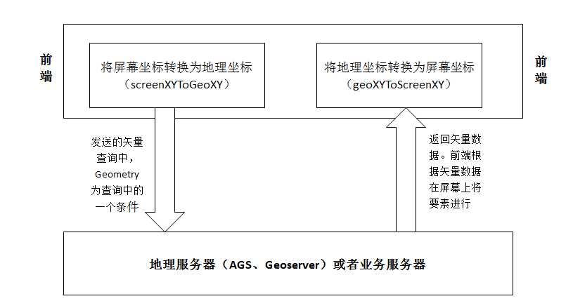
These two conversion formulas are often used in conjunction. For example, there is a requirement: after clicking on the map, you need to query the feature attribute information at the mouse click, and draw the features to the query on the map (in fact, this requirement is the requirement of an I query). Our implementation is to first convert the screen coordinates at the mouse click to the geographic coordinates, then add tolerance and then spell into a Geometry range, from the front end to issue the Request URL of the I query, through the geographic server to get the returned vector data, Then on the front end, the geographic coordinates in the vector data are converted to the screen coordinates, according to which features are plotted in UI Component, and the Atrributes carried in the vector data are parsed as the property data obtained by the query.
Here’s a flowchart for this process:
10.6. Summary
In this chapter, we know how to convert the geographic coordinates in the obtained vector data into screen coordinates. The next thing we need to do is to draw the shape of the feature based on the obtained screen coordinates in UIComponent. After understanding the acquisition method of vector numbers and the usage of vector data, we can finally design the elements and design the vector layer in the next two chapters. Everyone is welcome to continue to pay attention.