Some Elements of Photogrammetry
The concept of scale is spelled out and the factors that determine a given scale - including camera focal length and height above the ground - are considered, particularly in terms of formulae for calculating the scale when these parameters are inserted. The ways in which spatial resolution can be determined are discussed. The point is made also that large scale imagery, especially, experiences displacements and distortions increasing from center outwards.
Some Elements of Photogrammetry
Let’s move now from the spectral part of photogrammetry to the spatial part. Scale, mentioned before, is just the comparison of the dimensions of an object or feature in a photo or map to its actual dimensions in the target. We state scale in several ways, such as, “six inches to the mile”, “1/20,000”, and, most common “1:2,000”. These mean that one measurement unit in the numerator (image or map) is equivalent to the stated number of that unit in the denominator (scene). Thus, 1:2,000 simply states that one of any length unit, such as an inch, in the photo corresponds to 2,000 inches on the ground or air (cloud). Or, one cm is equivalent to 20,000 cm. “six inches to the mile” translates to six inches in the photo represents 63,360 (5,280 ft x 12 in/ft) inches in the real world, but we can further reduce it to 1:10,560, because six and 63,360 are divisible by six. Note that, if we enlarge or contract a photo of a given scale, say by projection as a transparency onto a screen, then one inch on the screen no longer corresponds to the same denominator number but now represents some other scale determined by the magnification factor. However, the effective resolution, the area covered, and the relative details remain the same.
We determine the scale of the aerial photo, expressed as its Representative Fraction (RF) by the height of the moving platform and by the focal length of the camera, according to this equation: RF = f/H*, where H* = H - h, with H = height (elevation with reference to sea level) of the camera and h is the height of a reference point on the surface, so that H - h is the distance between the platform and the point (assuming a flat ground surface; in rugged terrain, scale in effect varies with the elevations). We can also show that RF is also proportional to resolution and distance ratios, as given by RF = rg/rs = d/D, where rg is ground resolution (in line pairs per meter; see below) and rs is the sensor system resolution (in line pairs per millimeter); d is the distance between two points in the photo and D is the actual distance between these points on the ground (the definition of scale).
Several more questions will help to master these ideas.
` <>`__10-7: A map has a scale of 9.0 inches to the mile. What is the denominator of the RF? `ANSWER <Sect10_answers.html#10-7>`__
` <>`__10-8: Two points appear on a map 1.75 inches apart. The actual horizontal ground distance between the two points is 1108.0 meters. What is the denominator of the scale fraction (RF) for this map? `ANSWER <Sect10_answers.html#10-8>`__
` <>`__10-9: Points A and B are 2.2 inches apart on a map having a RF = 1/20000. They are 6.83 inches apart on an airphoto. What is the scale of the airphoto? `ANSWER <Sect10_answers.html#10-9>`__
` <>`__10-10: A vertical airphoto is taken from a flying height of 5000 ft relative to the ocean with a camera having a focal length of 6 inches. The flat surface is 1000 ft above sealevel. What is the RF for the resulting photo? `ANSWER <Sect10_answers.html#10-10>`__
` <>`__10-11: An aerial camera has a 9 1/2 inch square film format and a 6 inch focal length lens. What must the flying height (in meters) be to obtain a scale (RF) of 1/2000? `ANSWER <Sect10_answers.html#10-11>`__
We can elucidate the roles of f and H* further with the aid of the next diagram, which, although not strictly correct in terms of optics and simplified to two dimensions, does allow us to visualize the effects of changing focal length and platform height:
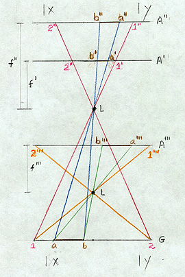
Lines such as 1-1” or a-a’ are light rays passing through the lens L. G is the ground. A’ is at the focal plane (holding the film) for a focal length of f ‘, and A” is the shift of this plane to a new value of f “. A”’ is the location of the focal plane for a case in which the lens, L, is now at a lower elevation. A line on the ground, a-b, passing through lens, L, is focused on plane A’, such that, it has a film dimension of b’-a’ (note that it is reversed in position but this does not matter because we can turn over a transparent negative). When we lengthen the focal length to f” to bring the focus onto A”, b’-a’ expands to b”-a”. Look next at what happens when we lower the camera (and airplane) to the A”’ position: a-b in this new arrangement (where L, the lens location relative to the film is the same distance as case 1, so that the focus, or focal length, is once more f ‘, i.e., f”’ = f’), now is expressed by b’’’-a’’’, which for these conditions is even longer than b”-a”. In these situations the frame size of the film (x-y in the two dimensional simplification) remains the same. Therefore, when x-y is at the A” location, the fraction of the scene imaged decreases by the loss of the outer parts and b”-a” occupies a larger segment of it. In the A”’ case, the size of film needed to display all of 1-2 is even greater, so that x-y now encloses even less of the scene. The A”’ image, held to the x-y limit, is larger scale than an A’ image and the A” image is also larger. Keep in mind that the dimensions shown on the line G are ground-sized, whereas those in A’, A”, and A”’ are film-sized, reduced relative to ground distances by the scales of the photographs.
We summarize these relations in a mnemonic:
Long is large/low is large/and larger is smaller.
Interpret this as follows: the scale is larger (denominator becomes smaller) as we lengthen the focal length or as we lower the platform. A large(r) scale image covers a small(er) ground area (with increased resolution). To appreciate how scale affects scene content, you may return to the various photos that we brought on-line in the previous page. The scale of each is printed alongside it.
Resolution has a popular meaning but is best defined in a technical sense. We normally think of resolution as the ability to separate and distinguish adjacent objects or items in a scene, be it in a photo or real life. We specify the resolution in terms of the smallest features we can discriminate. But, contrast influences resolution. If two items are the same color, they may be hard to separate, but if they are sharply different in color, tone, or brightness, we can identify them more easily. Shape also is a factor. So, a rigorous definition of resolution relies on the ability to separate adjacent alternating black and white thin lines in a target. The resolution of a film is determined in a laboratory by photographing placard-sized charts like the one shown below containing black lines with different spacings on a white background (or the reverse). Then, the resolution is the smallest spacing, in which we can discriminate pairs. This, of course, varies with distance between camera and target.
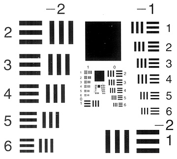
The separation between light-dark lines varies in this target. The spatial frequency of these alternating lines can be given in lines pairs/unit distance (width). The sharp light-dark pattern can be approximated by sinusoidal waves of specified frequencies; a common measure is given in cycles/millimeter. Depending on relative brightnesses between the lines in a pair (or contrasting objects in a real scene), the brightness amplitude between peak and trough of the waves will vary or modulate. A technically more exacting measure of resolution is given by the Modulation Transfer Function (MTF) - this plots modulation (ratio of target amplitudes to sensor [film; electronic] amplitudes) against spatial frequency. For the human eye as a sensor, its ability to separate colors is optimal at low frequencies (wider spacings) and falls off rapidly at frequencies greater than 2 cycles per retinal degree (spacings closer than about 0.2 mm); black and white pairs are optimally separated at 7 cycles per degree (about 0.05 mm) and fall off notably at both higher and lower frequencies. As one would expect, film MTFs are near maximum at low frequencies and drop progressively at higher frequencies.
(Note for the record: In real scenes, light reaching the film or sensor will consist of bundles of varying wavelengths (spectrally diverse) that act as a collection of different sine waves. To specify their influence on the recording medium, such as film, they can be subject to a procedure called Fourier Analysis which breaks them systematically into the actual wavelengths and amplitudes present. This is often applied when the spatial domain (variations of tonal patterns) of an image is being studied in scene interpretation. See pages 506-507 of Lillesand and Kiefer, Remote Sensing and Image Interpretaton, 5th Ed., J. Wiley, 2000 for a brief overview of this subject.)
In practice, we could place a resolution target in a scene (for example, painting black lines with different spacing on a concrete airport runway or road) to determine resolution for aerial conditions. Ground resolution is then the number of black/white line pairs within some width (normally one meter) that we can just discern in aerial photos taken at a particular height. Depending on the camera, film-resolving power, and platform height (the system), in the photo, the pair will either blend visually (not resolvable) or can be distinguished. We express system resolution, rs, (in which we combine the effects of sensor and film factors) in line pairs/mm within the print. A formula for ground resolution, rg, (in line pairs/meter), applicable to just separable ground lines, is:rg = f x rs/H. A typical example is a case where the lens focal length is 150 mm, the system resolution is 60 line pairs/mm, and the height is 3,000 meters, so that Rg is 3 line pairs/meter. From the relation 1 line pair/rg = width on ground of 1 line pair, this width is 0.33 m (each line is half that value). This means that the airborne camera can resolve an object on the ground that has a dimension of 0.165 m (about 6.5 inches), if it contrasts with its surroundings, using a film of appropriate resolving power. If the aircraft were flying higher, the camera could not detect this sized object.
` <>`__10-12: Given a camera with the focal length of 9 inches, capable of a photo resolution of 15 line-pairs per millimeter, when flown at an altitude of 12000 ft, what is the equivalent resolution on the ground? `ANSWER <Sect10_answers.html#10-12>`__
` <>`__10-13: What is the photo (system) resolution obtained when a camera with focal length of 120 mm is flown at an altitude of 6000 meters; the line-pair in a calibration target on the ground has a spacing of 4 line-pairs/m. `ANSWER <Sect10_answers.html#10-13>`__
Resolution in film (negatives and prints) is governed, in part, by the size distribution of the silver grains. In Landsat’s Multispectral Scanner/Thematic Mapper (MSS/TM), and other electronic sensors, image resolution ties closely to the size of the pixels or to the dimensions of individual detectors in the arrays of Charge-Coupled Detectors (CCDs), such as on SPOT. At first thought, it would seem that we cannot resolve objects smaller than the ground dimensions represented in an individual pixel/detector. However, if the spectral characteristics of a subresolution spot on the ground are sufficiently different from surrounding areas, they can affect the average brightness of the pixel so that the spot is visible in the image. An example of this are roads that are narrower than a 30 m (98 ft) TM pixel, yet are quite visible in a TM image.
In an aerial photo, when we view features at ground points off the principal point (optical center, usually at nadir or normal to a flat surface), that is, along slant directions, they may appear to lean away from the center, especially if they are tall (e.g., buildings) or have high relief. This distortion is worse if the aircraft flies low to acquire large scale photos. This is one type of displacement, and is evident near the edges in the 1:4,000 aerial photo of a neighborhood in Harrisburg, shown on page 10-1. We consider other modes of displacement, such as apparent lateral movements of image points along slopes of differing angles, in Section 11, page 11-4, which explores 3-D aspects relevant to stereo viewing and photogrammetric mapping.
We can fly aerial photo missions at any time during the day, but they usually occur between about 10:00 AM and 2:00 PM (in summer to avoid afternoon storms). Typically, the aircraft traverses the region to be photographed along back-and-forth flight lines and acquires pictures at intervals that allow about 50% overlap between successive photos and 20% to 50% sidelap between lines. The camera usually mounts below the plane, near its nose. Film in the camera advances automatically at time intervals that are synchronized with the speed of the aircraft. Especially in color photos, but also in black and white photos, blue and ultraviolet light that is scattered by the atmosphere may degrade the film image. We can reduce this degradation by using a haze filter that absorbs the ultraviolet and the very shortest visible blue wavelengths.
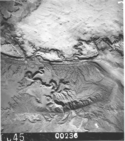
NASA has a stable of support aircraft that operate various sensors, including cameras, to gather ground reference data for remote sensing experiments (see page 13-4 which discusses this). An example of a small-scale image (about 1:150,000) obtained during a U-2 flight, which operated at an altitude of about 18,000 m (59,000 ft) over Utah (resolution about 5 meters), closes this section on aerial photography.
For anyone interested in viewing more aerial-type photos, including perhaps one of a home region, consult the on-line Net Home Page called “TerraServer”, sponsored by Microsoft. Aerial imagery, either individual photos or sections of orthophotoquads, of selected large parts of the United States, has been digitized from data collected by the U.S. Geological Survey. Their resolution ranges from less than 2 to about 12 meters. Imagery taken with the KVR-1000 camera (resolution: 2 meters) flown on several Russian satellites shows regions in the rest of the world, mainly in Europe. They market these data worldwide as part of their SPIN-2 program. All photos are black and white.
Of course, the principles we have been applying in these three pages to aerial photos pertain in many respects to space imagery as well. Mapping once done primarily with air photos can now be done almost as well with space products. The main drawback is resolution, and that limitation is rapidly disappearing with the declassification of high resolution military imagery and with the ever-improving resolution capability of satellites now being flown or on the drawing boards for the foreseeable future. As we shall see in the next Section, the ability to gather data from space that pertain to three-dimensional surface variations allows the mapping community to essentially duplicate all the advantages once exclusive to air-based photography.