Thermal Properties of Water
Contents
This page treats several subjects. First, the thermal behavior of water is examined. Then, the nature of thermal sensors, in terms of detectors and their environment and operational conditions from air or space platforms, is investigated.
Thermal Properties of Water
Water has very dark to medium gray tones in day thermal-IR images and moderately light tones in night thermal images, compared with the land. This response is due in part to a rather high thermal inertia, relative to typical land surfaces, as controlled largely by water’s high specific heat. Thus, it heats less during the day and holds that heat more at night (an obvious condition swimmers experience), giving rise under many meteorological conditions to intrinsic cooler daytime temperatures and often warmer nighttime temperatures than most materials on land. Also, being nonsolid, water in natural settings (rivers, lakes, oceans) is likely to experience disruption of its thermal gradient by convection (e.g., upwelling) and turbulence (e.g., wave action) that tend towards mixing and homogenation, so that its near-surface temperatures vary by only a few degrees at most (temperature “smoothing”).
As discussed on the previous page, the appearance in thermal images of both water and land depend on the time of day. Below is a sequence of 4 thermal images taken by an airborne Daedalus thermal scanner that show a land area next to the Delaware River, on the New Jersey side.
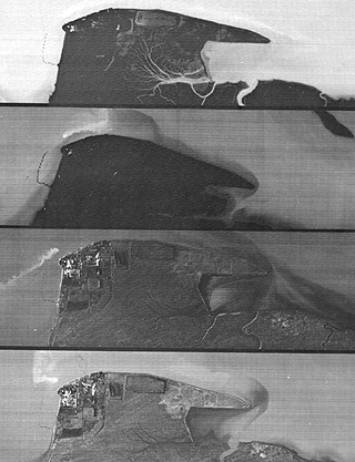
The images were processed to emphasize water differences, thus subduing the land expression of thermal variability. The top three images were taken on December 28, 1979. The first on top was acquired during a pass at 06:00 hours when the air temperature was -9° C; the water relative to land was notably warmer (above freezing). The second image was obtained at 08:00 with the water still warmer than the land; the bright streak near the land’s upper left point is hot effluent from a power plant. At 14:00 hours (3rd strip), the air temperature had climbed to -2° C and thermal contrast between land and water is near minimal; note the detail evident in the power plant; the effluent is now pointing downstream as ebb tide occurs. The power plant detail persists in the bottom image, taken on December 29th at 11:00 when the air temperature was -4°: C. and the tide was near high. The scenes taken at different times and dates show the temperature variations that occur in the river water, and to a lesser extent on the land
As we saw on page 3-1, water in moist soils tends to keep them cooler than drier soils, so that black and white thermal images show darker patterns where the amount of moisture is higher.
Thermal Sensors
Some reminders about thermal sensors: For scanners designed to sense in the 8 to 14 µm interval, the detector is usually an alloy of mercury-cadmium-tellurium (HgCdTe) that acts as a photoconductor in response to incoming photons in this thermal energy range. Mercury-doped germanium (Ge(Hg)) is also used for this interval, although it is effective over a broader range, down to about 2 µm. Over the 3-5 µm interval, indium-antimony (InSb) is the alloy we use in detectors operating in that range. Efficient operation requires onboard cooling of this detector to temperatures between 30° and 77° K, depending on the detector type. We maintain this temperature range either with cooling agents, such as liquid nitrogen or helium (in a container called a Dewar, that encloses the detector) or, for some spacecraft designs, with radiant cooling systems that take advantage of the cold vacuum of outer space. Detectors need this cooling to improve their signal-to-noise (S/N) ratio to a level at which they have a stable signal response. This signal is, of course, an electrical current related to changes in detector resistance that are proportional to the radiant energy.
To obtain a quantitative expression of radiant temperatures, we must calibrate the detector response. We use calibration sources (e.g., thermistors) at different temperatures near the extremes we expect from the ground to provide a correction function. The scanner normally has a glow tube or other device in which a wire passes a current that causes it to glow (giving off radiant energy) at some temperature. We commonly use two such thermistors: one glowing at a temperature near the low value anticipated from most targets, and the other glowing near the high value. We usually determine these temperature/radiance relations in advance in the laboratory, prior to the scanner becoming operational. Aircraft scanners require periodic recalibration.
In operation, the image signal goes either to a separate recording unit or through a chopper for sampling from the main beam. The radiant temperatures are not normally converted to kinetic temperatures because we don’t usually know the emissivities of the diverse surface materials sufficiently well to permit this.
9-11: What is an obvious disadvantage to the use of electric temperature devices, such as lamps, in spacecraft thermal sensors as a means of calibration? `ANSWER <Sect9_answers.html#9-11>`__
Now that we’ve warmed up to this subject, lets look at some notably hot images, unless you decide to cool it and go on to something else!

Primary Author: Nicholas M. Short, Sr. email: nmshort@nationi.net