Radar Polarization (Harrisburg, PA); Penetration of Foliage
Contents
The mode of polarization in the outgoing signal, and then its interaction with the target, will determine the compound polarization of the returned signal. A parameter called the dielectric constant has an effect on the intensity of signal return.Surface roughness also affects the signal character. Depending on radar wavelength and on the size/shape aspects of target features, different radar bands have differing degrees of penetrability through clouds, forest canopy, and surface materials.
Radar Polarization (Harrisburg, PA); Penetration of Foliage
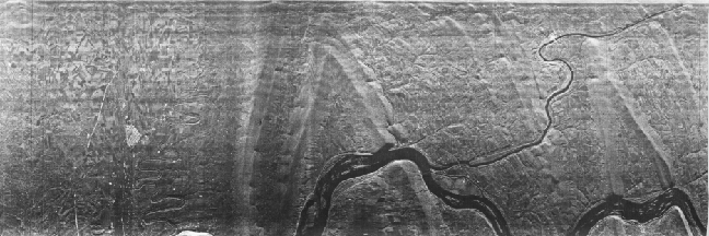
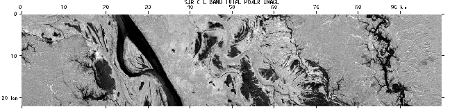
` <>`__8-13: Describe the principal differences you note between the HV and HH modes. `ANSWER <Sect8_answers.html#8-13>`__**
Other factors contribute to the brightness or intensity of the returned signal. Two material properties provide clues about composition and surface state by the manner in which these attributes interact with the incoming pulses. One property is the dielectric constant (its symbol is the small Greek letter, κ, kappa), which is the ratio of the capacitance of a material to that of a vacuum (yielding dimensionless numbers; the value of κ is arbitrarily set to 1 for a vacuum). It is a measure of both the conductivity and reflectivity in terms of the electrical response of materials. This electrical property describes a material’s capability (capacity) to hold a charge, which also measures the material’s ability to polarize when subjected to an electric field. Radar waves penetrate deeper into materials with low dielectric constants and reflect more efficiently from those with high constants. Values for κ range from 3 to 16 for most dry rocks and soils, and up to 80 for water with impurities. Moist soils have values typically between 30 and 60. Thus, variation in reflected-pulse intensities may indicate differences in soil moisture, other factors being constant. Variations among rocks is generally too small to distinguish most types by this property alone.
The second material property is roughness. Materials differ from one another in their natural or cultivated state of surface roughness. Roughness, in this sense, refers to minute irregularities that relate either to textures of the surfaces or of objects on them (such as, closely-spaced vegetation that may have a variety of shapes). Examples include the surficial character of pitted materials, granular soils, gravel, grass blades, and other covering objects whose surfaces have dimensional variability on the order of millimeters to centimeters. The height of an irregularity, together with radar wavelength and grazing angle at the point of contact, determines the behavior of a surface as smooth (specular reflector), intermediate, or rough (diffuse reflector). To quantify the effect of different wave bands, a surface with a given small irregularity height (in cm) will reflect Ka band (λ = 0.85 cm), X band (λ = 3 cm), and L band ( λ = 25 cm) radar waves as if it were a smooth, intermediate, and rough surface, respectively. Other average heights produce different responses, from combinations of “all smooth” to “all rough” for the several bands used. This situation means a radar, broadcasting three bands simultaneously in a quasi-multispectral mode, can produce color composites, if we assign a color to each band (see below). Patterns of relative intensities (gray levels) for images made from different bands may serve as diagnostic tonal signatures for diverse materials whose surfaces show contrasted roughness.
Radar Penetration
>